<aside> ‼️ This manual was taken from the Church of the Highlands production team manuals and modified for our use.
</aside>
The last couple of lessons we have looked at our Audio Environment, the big pieces that make up a sound system and signal flow. Today, we will concentrate on how to make all of these pieces come together and actually get the sound from our stage (sources), through the mixer(s), into the processor and finally out of the different speakers. This will be the process we will refer to as Integration. In other words, we will be putting all of these different components together. As we integrate these components, we will need to interconnect different pieces of gear. We will refer to the result of this interconnection pathway as creating a signal chain. Just like a chain has connected links, so a sound system must have methods of connecting different pieces of equipment together. I know most of you have heard the adage, “a chain is only as strong as its weakest link?” This can also be the case with our signal chain. Through our process, we may discover a few places where these weak links may be, how to identify them and a best course of action for solving a problem.
First, we will look at the wire, connectors and cabling necessary in interconnecting all of our gear. Then, we will look at how the different pieces come together to create a working system.
Let’s start out with one of the most basic and fundamental tools used in the integration of the many components in a sound system, copper wire. "Copper" can be a relative term, but is commonly accepted terminology for any wire carrying an analog signal.
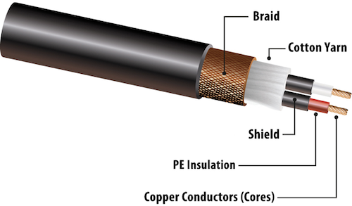
This illustration is a great example of what might be used for a balanced microphone cable. The outer jacket can be composed of anything from a very flexible rubber to an extremely durable PVC jacket. Just inside that jacket will be some type of shielding. In this illustration, this shielding is a copper braid. Other common shielding materials may include foil or even a high-tech conductive plastic shielding. Next you will see the cotton yarn, which is actually only a filler product. This usually insures a nice round cable. In this illustration the two conductors--with red and white jackets-- have an additional layer of shielding (hi-tech conductive plastic) and are comprised multi-strand copper wire.

Here we have an unbalanced (High impedance) cable. This type of cable is most commonly used as an instrument cable. One very important thing to remember about unbalanced instrument cables is that their length should be limited to 25' or less. Since the signal is unbalanced, it is more susceptible to outside interference. If your cable run needs to be longer than 25', you should use some type of interface device such as a DI (direct insertion) box or SGI system. We'll talk more about these as we dig into integrating our gear.
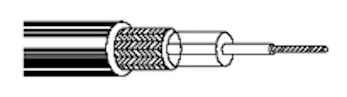
Gepco GLC20
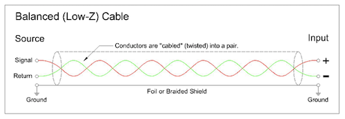
Here are representations of a balanced cable. In that we have both a positive and a negative audio signal traveling the cable, we may have much longer cable runs. This is why we tend to convert unbalanced signals into balanced signals in order to run longer distances.
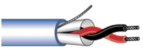
Gepco XB201M
Even though this illustration shows the shield/ground wire as "floated" or not connected, for practical purposes we DO connect them these days. However, in certain circumstances, we may still "float" the ground when using a balanced cable as a "drive" line.